






Quick Reminder: What Is Voltage Drop?
Voltage drop is voltage lost as current flows through resistance in conductors, connections, switches, fuses, circuit breakers, and other components.
Ohm’s Law explains the relationship:
Voltage = Current × Resistance (V = I × R)
Even a small amount of unwanted resistance can create significant voltage drop when enough current is flowing.
Voltage Drop Testing Must Be Done Under Load
Voltage drop testing should be performed while the circuit is operating. Remember, if there is no current, there is no voltage drop.
A loose or corroded connection may show nearly full system voltage with the equipment off. Once the equipment is turned on and current flows, that resistance can cause a measurable voltage loss.
This is why voltage drop testing can reveal problems that a basic voltage or continuity test may miss.
What You Need
A digital multimeter set to DC volts is all that is required.
Start by Checking the Entire Circuit
Using a 12 VDC system as an example*:
- Source voltage: 12.0 V
- Voltage at the operating load: 11.4 V
Total voltage drop:
12.0 V − 11.4 V = 0.6 V
Percentage voltage drop:
0.6 ÷ 12.0 × 100 = 5%
You can determine total circuit voltage drop by:
- Measuring voltage across the source terminals and then across the load terminals, and subtracting the load voltage from the source voltage.
- Measuring voltage drop on the positive and negative sides separately, then adding the two readings.
If excessive voltage drop is found, you can narrow down where it occurs.
Test the Positive Side
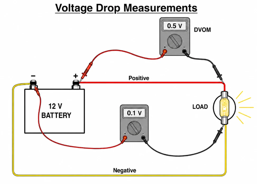
With the equipment operating, place the red probe on the positive source terminal and the black probe on the positive terminal of the load.
The reading represents voltage lost through the positive side wiring, fuses, breakers, switches, terminals, splices, and connections.
If the meter reads 0.5 V, test smaller sections; across a fuse, breaker, switch, conductor, terminal, splice, or connector; until the excessive drop is isolated.
Test the Negative Side
Place the red probe on the negative terminal of the load and the black probe on the negative source terminal.
If the positive side drops 0.5 V and the negative side drops 0.1 V:
0.5 V + 0.1 V = 0.6 V total voltage drop
Most of the unwanted resistance is therefore on the positive side.
Test Individual Connections
Measure directly across a connection or component while current is flowing. A good connection should show very little voltage drop.
Loose, corroded, or poorly made connections can create significant voltage loss and may also generate heat.
Voltage drop testing is one of the simplest and most effective ways to locate resistance problems in a boat’s DC electrical system.
*Values are for illustration only. A 12 V battery is a nominal rating; actual voltage varies with battery chemistry, state of charge, charging conditions, and load.
Safety Disclaimer: Voltage drop testing requires an energized circuit operating under load. Testing should only be performed by persons familiar with electrical safety practices and proper multimeter use. If you are unsure how to perform a test safely or interpret the results, consult an ABYC Certified Technician.
If you would like to learn more tips, troubleshooting methods, and multimeter basics, contact ABYC Standards and Compliance Department at [email protected]. For additional information, refer to ABYC E-11, AC and DC Electrical Systems on Boats.